Tools needed Herramientas necesarias
- Wire crimpers & cutters
- Wire stripper
- Digital Volt Meter
- Multi-bit Screwdriver
- Socket Wrench
- 2x Add-A-Fuse
- Prensador de alambre
- Pelacables
- Voltímetro digital
- Destornillador multipunta
- Llave de tubo
- 2x Add-A-Fuse
Installation steps Pasos de instalación
1. Scan the device barcode or type it in manually.
1. Escanee el código de barras del dispositivo o ingréselo manualmente.
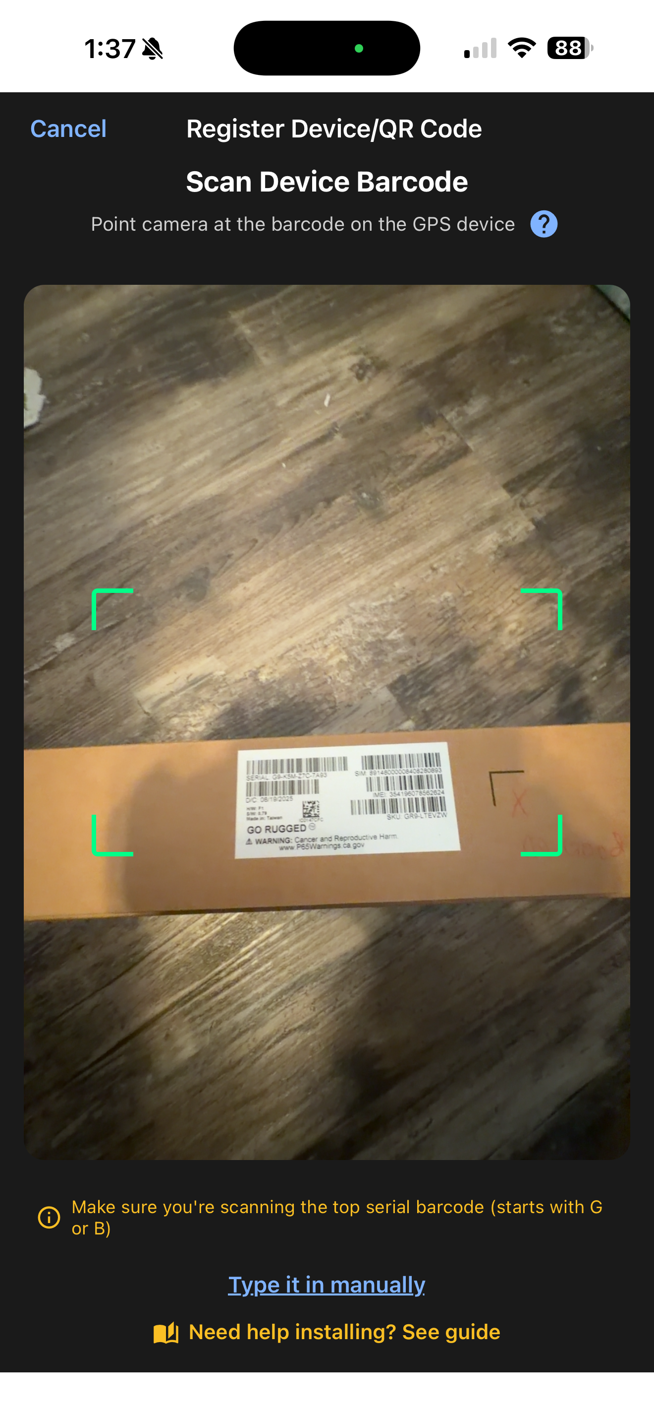
⚠ If the device is not synced to your account you will see a "Device not in your account" message — contact support to get it synced.
⚠ Si el dispositivo no está sincronizado con su cuenta verá el mensaje "Dispositivo no está en su cuenta" — comuníquese con soporte para sincronizarlo.
2. Fill in equipment details. The following are required: Equipment Name, Equipment Type, and Current Engine Hours.
2. Complete los detalles del equipo. Los siguientes son obligatorios: Nombre del equipo, Tipo de equipo y Horas actuales del motor.
3. Optional: Odometer reading, Make, Model, Year, VIN, Labels, and Notes.
3. Opcional: Lectura del odómetro, Marca, Modelo, Año, VIN, Etiquetas y Notas.
4. Press Update to save changes.
4. Presione Actualizar para guardar los cambios.
💡 At the top of the page you can also assign a QR code if you have one on hand.
💡 En la parte superior de la página también puede asignar un código QR si tiene uno a la mano.
3-wire harnesses are for equipment without J1939 ports. Common compatible equipment: Kubota, New Holland (pre-2021), older equipment. ⚠ Use J1939 harness for equipment with a J1939 port.
Los arneses de 3 cables son para equipo sin puerto J1939. Equipo compatible común: Kubota, New Holland (antes de 2021), equipo más antiguo. ⚠ Use el arnés J1939 para equipo con puerto J1939.
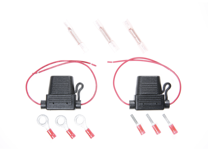
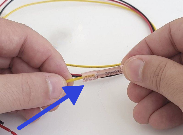
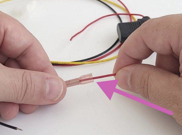
Repeat the above steps with the Red wires of the 3-wire harness.
Repita los pasos anteriores con los cables rojos del arnés de 3 cables.
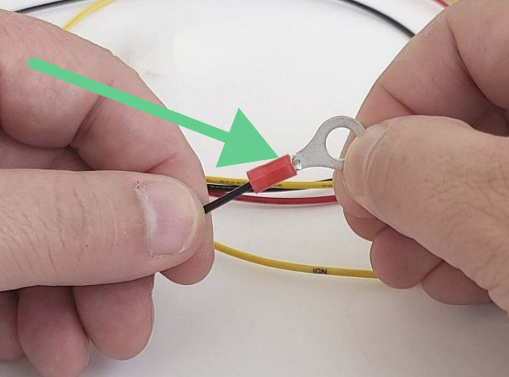
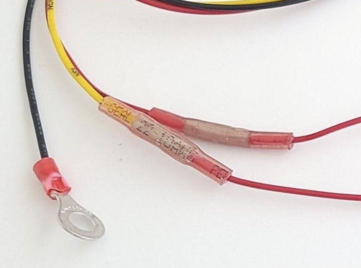
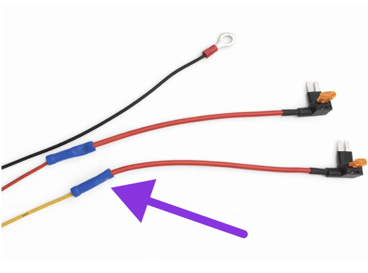
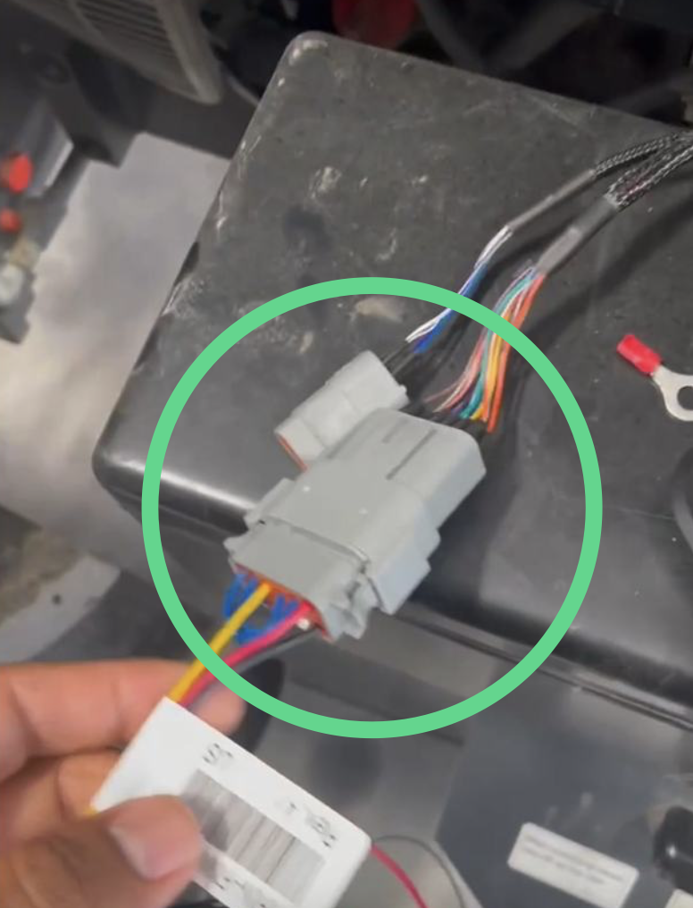
Connect the Deutsch connector of the assembled harness to the GPS device.
Conecte el conector Deutsch del arnés ensamblado al dispositivo GPS.
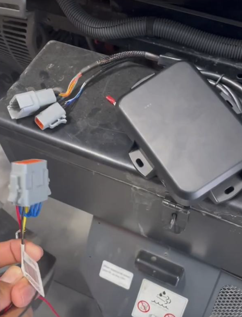
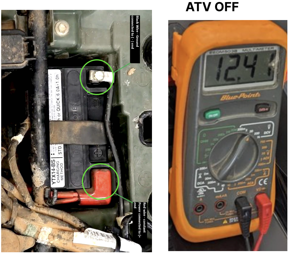
Locate a constant +12/24V battery source fuse in the equipment's fuse panel. Connect the red Add-A-Fuse to the equipment's constant power fuse. ① A suitable fuse will have +12/24V at all times, even when the equipment is OFF.
Localice un fusible de fuente de batería constante +12/24V en el panel de fusibles del equipo. Conecte el Add-A-Fuse rojo al fusible de potencia constante del equipo. ① Un fusible adecuado tendrá +12/24V en todo momento, incluso con el equipo apagado.
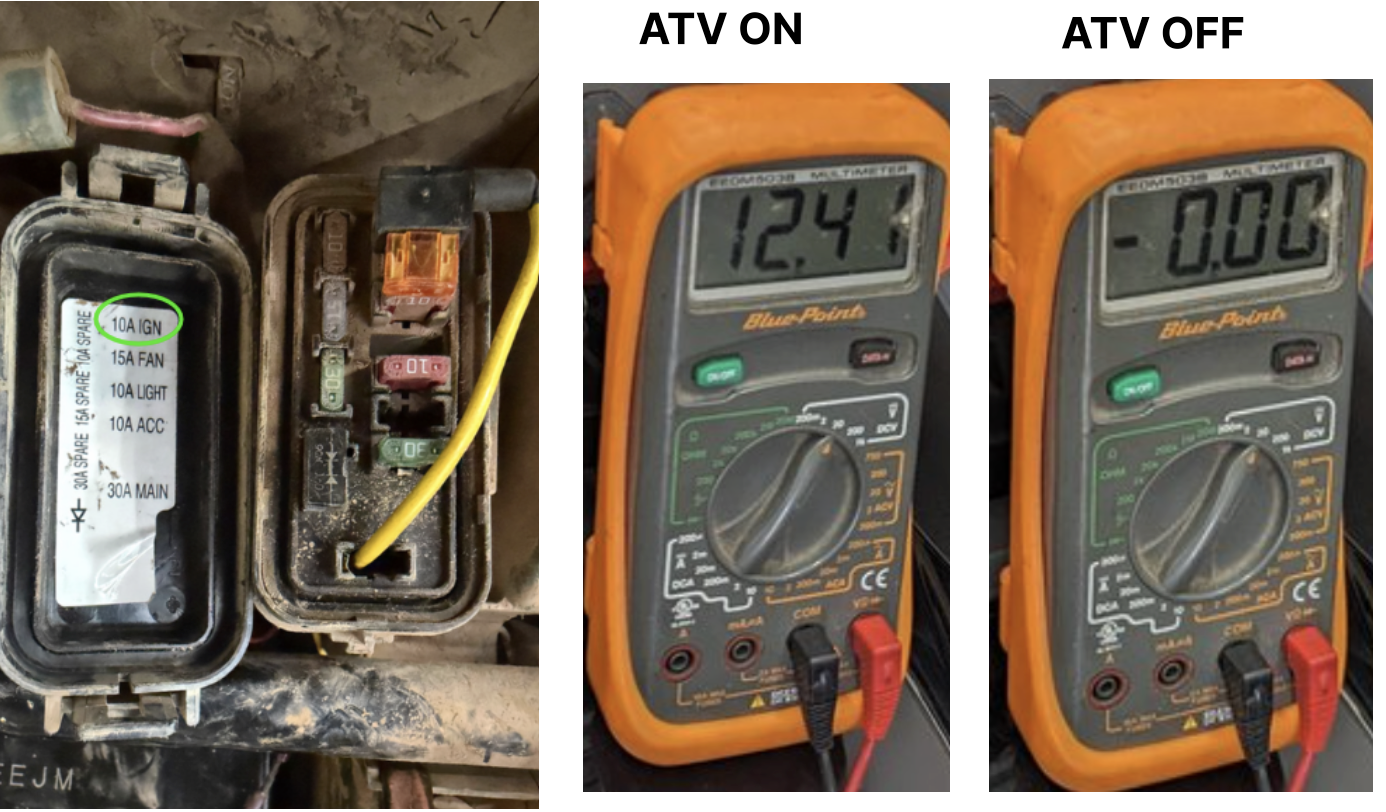
Locate a +12/24V ignition power fuse. Connect the yellow Add-A-Fuse to the equipment's ignition fuse. ⚠ Should read +12/24V when key is ON and 0V when key is OFF.
Localice un fusible de encendido +12/24V. Conecte el Add-A-Fuse amarillo al fusible de encendido del equipo. ⚠ Debe leer +12/24V con llave en ON y 0V con llave en OFF.
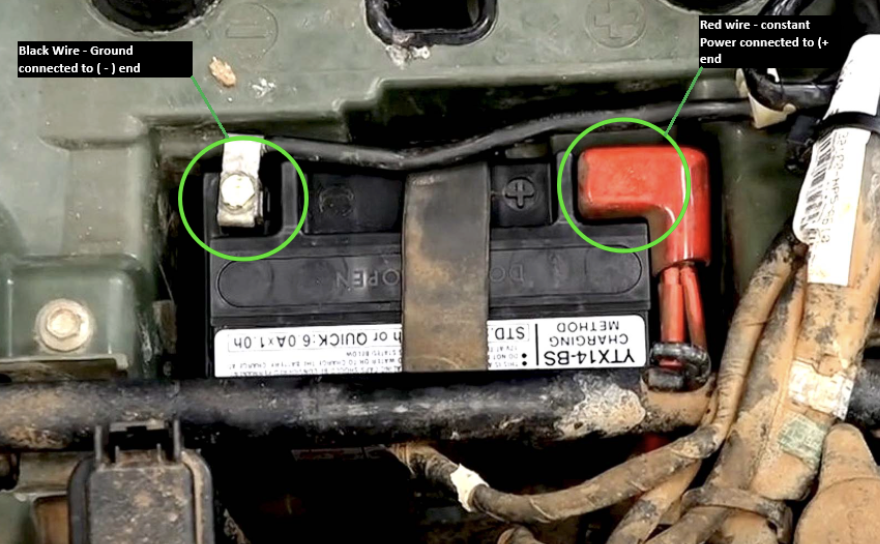
Connect the ring terminal to the negative battery end (-) using an existing screw or a self-tapping screw (not included). ⓘ The surface of the floor must be bare metal.
Conecte el terminal de anillo al extremo negativo (-) de la batería usando un tornillo existente o un tornillo autorroscante (no incluido). ⓘ La superficie del piso debe ser metal desnudo.
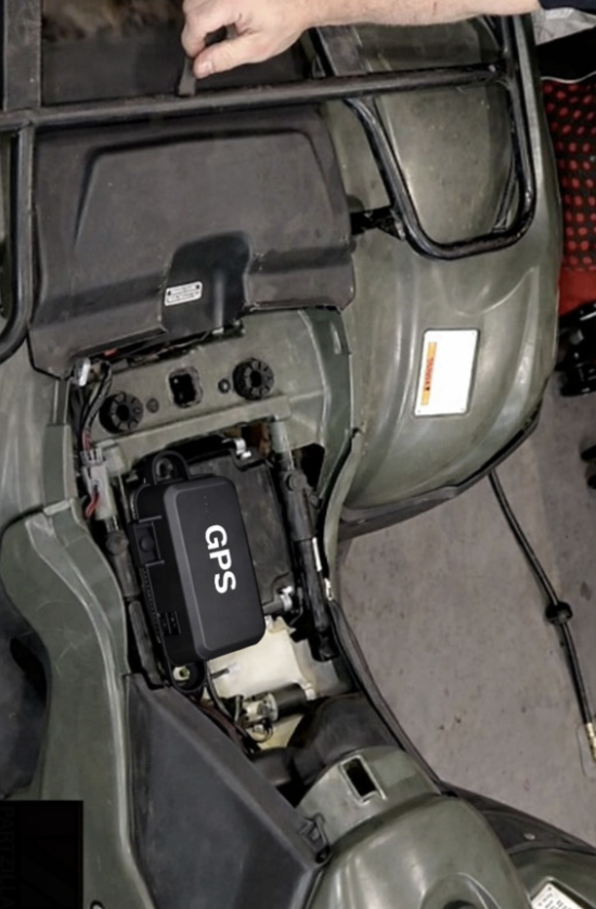
Secure device with self-tapping screws and/or zip ties. • Must be secured and stable.
Asegure el dispositivo con tornillos autorroscantes y/o bridas. • Debe estar asegurado y estable.
Start the equipment and verify the LED pattern. Allow up to 15 minutes for solid LEDs. ⚠ Drive the equipment outside the workshop to prevent the roof from interfering with the GPS signal. 🔴 Red blinking — firmware update pending 🔴 Red solid — firmware downloaded 🔵 Blue blinking — GPS on, not connected 🔵 Blue solid — GPS connected ✅ 🟢 Green blinking — cellular on, not connected 🟢 Green solid — cellular connected ✅
Arranque el equipo y verifique el patrón de LED. Espere hasta 15 minutos para LEDs sólidos. ⚠ Conduzca el equipo fuera del taller para evitar que el techo interfiera con la señal GPS. 🔴 Rojo parpadeando — actualización de firmware pendiente 🔴 Rojo sólido — firmware descargado 🔵 Azul parpadeando — GPS encendido, no conectado 🔵 Azul sólido — GPS conectado ✅ 🟢 Verde parpadeando — celular encendido, no conectado 🟢 Verde sólido — celular conectado ✅
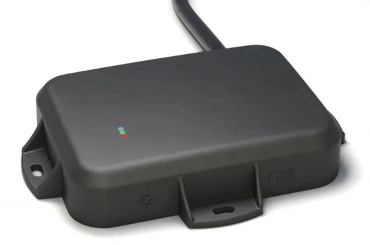
LED Quick Reference Referencia rápida de LEDs
| LEDLED | BlinkingParpadeando | SolidSólido |
|---|---|---|
| 🔴 RedRojo | Firmware updatingActualizando firmware | Firmware downloaded ✓Firmware descargado ✓ |
| 🔵 BlueAzul | GPS on, searchingGPS encendido, buscando | GPS connected ✓GPS conectado ✓ |
| 🟢 GreenVerde | Cellular searchingCelular buscando | Cellular connected ✓Celular conectado ✓ |
Common issues Problemas comunes
Device won't turn on El dispositivo no enciende
- Check physical connections. The red (power), black (ground), and yellow (ignition) wires must be securely connected, and the device firmly seated in the harness. Verifique las conexiones físicas. Los cables rojo (potencia), negro (tierra) y amarillo (encendido) deben estar bien conectados, y el dispositivo firmemente insertado en el arnés.
-
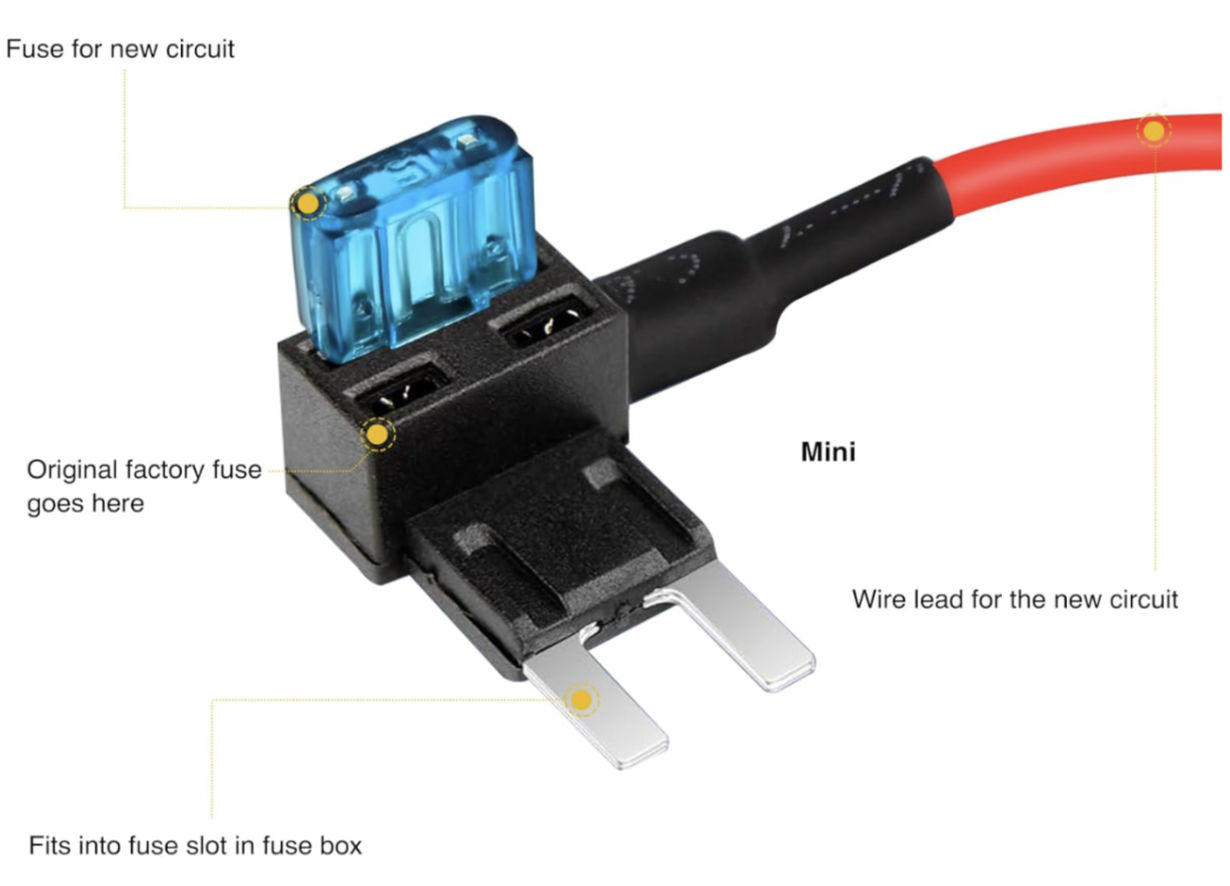
Check the inline fuses. A blown fuse is the most common cause of no power. Replace with the correct amperage if blown.The ORIGINAL factory fuse must be plugged into the Add-A-Fuse — if missing, neither the equipment accessory nor the GPS will work.The NEW fuse for the GPS circuit must be plugged into the Add-A-Fuse — if missing, the GPS will never turn on.Make sure the fuses haven't been SWAPPED by accident — a 5A fuse placed in a 30A slot will blow immediately.
Verifique los fusibles en línea. Un fusible quemado es la causa más común de falta de energía. Reemplace con el amperaje correcto si está quemado.El fusible ORIGINAL de fábrica debe estar conectado en el Add-A-Fuse — si falta, no funciona ni el accesorio del equipo ni el GPS.El fusible NUEVO para el circuito del GPS debe estar conectado en el Add-A-Fuse — si falta, el GPS nunca enciende.Verifique que los fusibles no se hayan INTERCAMBIADO por accidente — un fusible de 5A en una ranura de 30A se quemará de inmediato.
- Verify constant power (red wire). Using a voltmeter, confirm the red wire reads +12/24V at all times — even when the equipment is OFF. Verifique potencia constante (cable rojo). Con un voltímetro, confirme que el cable rojo lea +12/24V en todo momento — incluso con el equipo apagado.
- Check ground (black wire). Ensure the ring terminal is securely connected to the negative battery end (-) and the contact surface is bare metal. Verifique la tierra (cable negro). Asegúrese de que el terminal de anillo esté bien conectado al extremo negativo (-) de la batería y que la superficie de contacto sea metal desnudo.
- Hard reset / power cycle. Disconnect the device from the harness, wait 30 seconds, and reconnect. Reinicio forzado. Desconecte el dispositivo del arnés, espere 30 segundos y vuelva a conectar.
Vehicle has high idle or shows "always ON" El vehículo tiene ralentí alto o muestra "siempre encendido"
- Check the ignition wire (yellow). The yellow wire must be on a TRUE ignition source — +12/24V ONLY when the key is ON, and 0V when the key is OFF. Verifique el cable de encendido (amarillo). El cable amarillo debe estar en una fuente de encendido REAL — +12/24V SOLO con la llave encendida, y 0V con la llave apagada.
- Verify with a voltmeter. With the key OFF, the yellow wire should read 0V. If it reads +12/24V, it's on constant power — move it to a switched fuse. Verifique con un voltímetro. Con la llave apagada, el cable amarillo debe leer 0V. Si lee +12/24V, está en potencia constante — muévalo a un fusible conmutado.
- Check the fuse panel. Use radio, accessories, or IGNITION-labeled fuses. Avoid fuses labeled BATT or CONSTANT. Revise el panel de fusibles. Use fusibles de radio, accesorios o etiquetados IGNITION. Evite fusibles etiquetados BATT o CONSTANT.
🔵 GPS not connecting (Blue LED not solid) 🔵 GPS no conecta (LED azul no sólido)
- Check antenna orientation. The device must have a clear view of the sky. Mount on the exterior, not blocked by a metal roof or cab. Verifique la orientación de la antena. El dispositivo debe tener vista despejada del cielo. Monte en el exterior, sin bloqueo de techo metálico o cabina.
- Move outside the shop. Metal roofs block GPS. Drive at least 20 feet outside and wait up to 15 minutes. Salga del taller. Los techos metálicos bloquean el GPS. Conduzca al menos 6 metros afuera y espere hasta 15 minutos.
- Check for straight lines on the map. Straight-line tracks on the map indicate GPS signal loss — the device needs a clearer sky view. Busque líneas rectas en el mapa. Trayectos en línea recta en el mapa indican pérdida de señal GPS — el dispositivo necesita mejor vista del cielo.
- Drive around the shop. Drive slowly around the shop or yard. Movement helps the GPS lock onto satellites faster. Allow up to 15 minutes. Conduzca alrededor del taller. Conduzca lentamente alrededor del taller. El movimiento ayuda al GPS a fijar satélites más rápido. Espere hasta 15 minutos.
- Allow warm-up time. After a first install or reset, GPS can take up to 15 minutes for a solid fix. Permita tiempo de calentamiento. Tras la primera instalación o un reinicio, el GPS puede tardar hasta 15 minutos en obtener señal sólida.
🟢 Cellular not connecting (Green LED not solid) 🟢 Celular no conecta (LED verde no sólido)
- Check cellular coverage. Confirm the install location has cellular coverage. No cell service = no connection. Verifique la cobertura celular. Confirme que el lugar de instalación tenga cobertura celular. Sin servicio celular no hay conexión.
- Allow warm-up time. After powering on, the cellular modem can take up to 15 minutes to connect. Permita tiempo de calentamiento. Después de encender, el módem celular puede tardar hasta 15 minutos en conectarse.
- Check device mounting. If the device is inside a metal enclosure, the signal may be blocked. Reposition to a more exposed location. Verifique el montaje del dispositivo. Si el dispositivo está dentro de una caja metálica, la señal puede estar bloqueada. Reubíquelo a un lugar más expuesto.
- Scan the QR code to verify. Scan the QR code on the device label to check communication status in the portal. Escanee el código QR para verificar. Escanee el código QR en la etiqueta del dispositivo para verificar el estado de comunicación en el portal.
🔴 Red LED blinking — firmware update pending 🔴 LED rojo parpadeando — actualización de firmware pendiente
- This is normal. A blinking red LED means the device is downloading the latest firmware. Expected on a first install or after a reset. Esto es normal. Un LED rojo parpadeando significa que el dispositivo está descargando el firmware más reciente. Es normal en una primera instalación o tras un reinicio.
- Wait for solid red. Once the firmware downloads, the red LED turns solid. This can take 5–15 minutes. Keep the device powered. Espere el LED rojo sólido. Cuando el firmware termina de descargarse, el LED rojo se vuelve sólido. Puede tardar 5–15 minutos. Mantenga el dispositivo encendido.
- Do not disconnect. Do not disconnect while the red LED is blinking. Interrupting a firmware update can cause issues. No desconecte. No desconecte mientras el LED rojo parpadea. Interrumpir una actualización de firmware puede causar problemas.
Add-A-Fuse won't seat in the panel El Add-A-Fuse no encaja en el panel
Wrong size. Verify mini, micro, or standard ATC matches the equipment's fuse panel. Tamaño incorrecto. Verifique que mini, micro o ATC estándar coincida con el panel de fusibles del equipo.